Hardware Setup
Bitstream Evolution v1 — iCEstick
Before ordering any parts, please note that the current Bitstream Evolution toolchain supports Linux and macOS host machines. The steps below mirror the original hardware tutorial and walk through a low-cost way to assemble the evaluation platform.
Bill of Materials
| Item | Approx. Cost | Where to Purchase |
|---|---|---|
| Microcontroller (Arduino Nano compatible) | ~$10 | Arduino Nano Kit |
| Lattice iCEstick HX1K FPGA | ~$150 | Mouser iCE40HX1K-STICK-EVN |
| 2x40 male headers (soldered to FPGA) | ~$10 | Hammer Header Kit |
| Male-to-male jumper wires | ~$5 | Elegoo Jumpers |
| Male-to-female jumper wires | ~$5 | Elegoo Jumpers |
| Full-size breadboard | ~$10 | MCIGICM Breadboard 2-pack |
Total hardware cost: roughly $190 USD.
Assembly Steps
1. Inspect the Kit
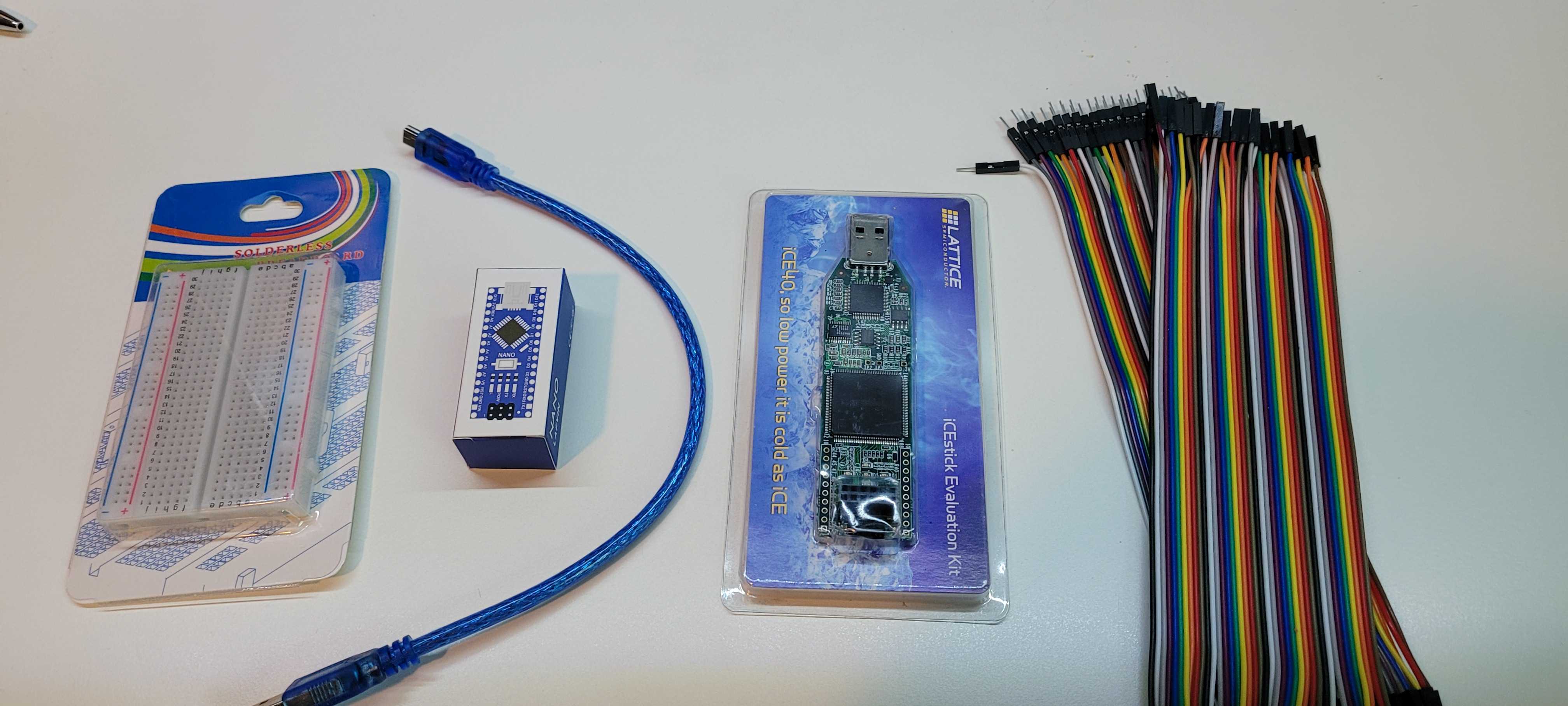
Verify that the MCU, FPGA, jumper wires, and breadboard all arrived intact before you begin.
2. Add Headers to the FPGA
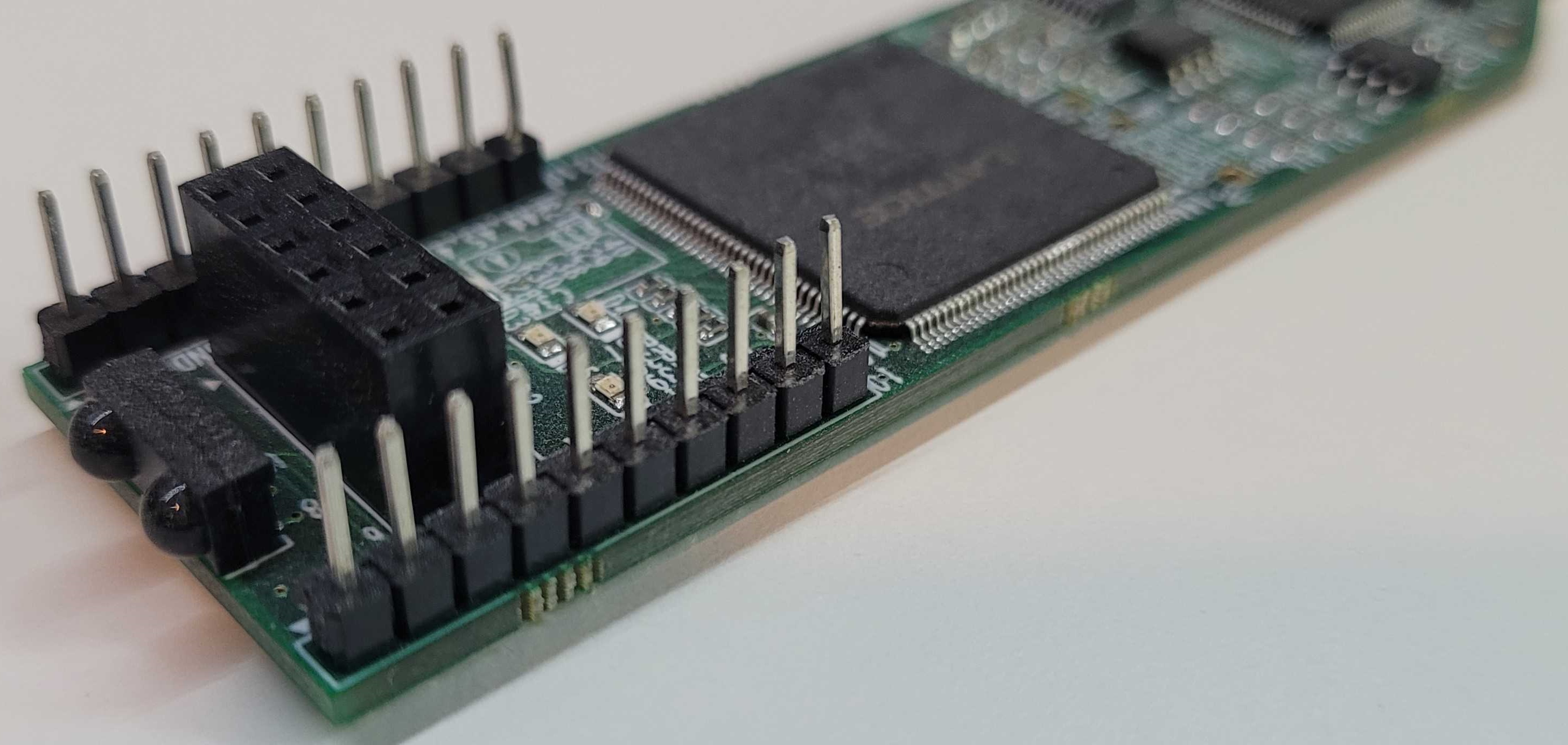
Solder (or press-fit hammer) headers onto both sides of the FPGA so that every I/O pin is accessible from the breadboard or jumper wires.
3. Seat the MCU in the Breadboard
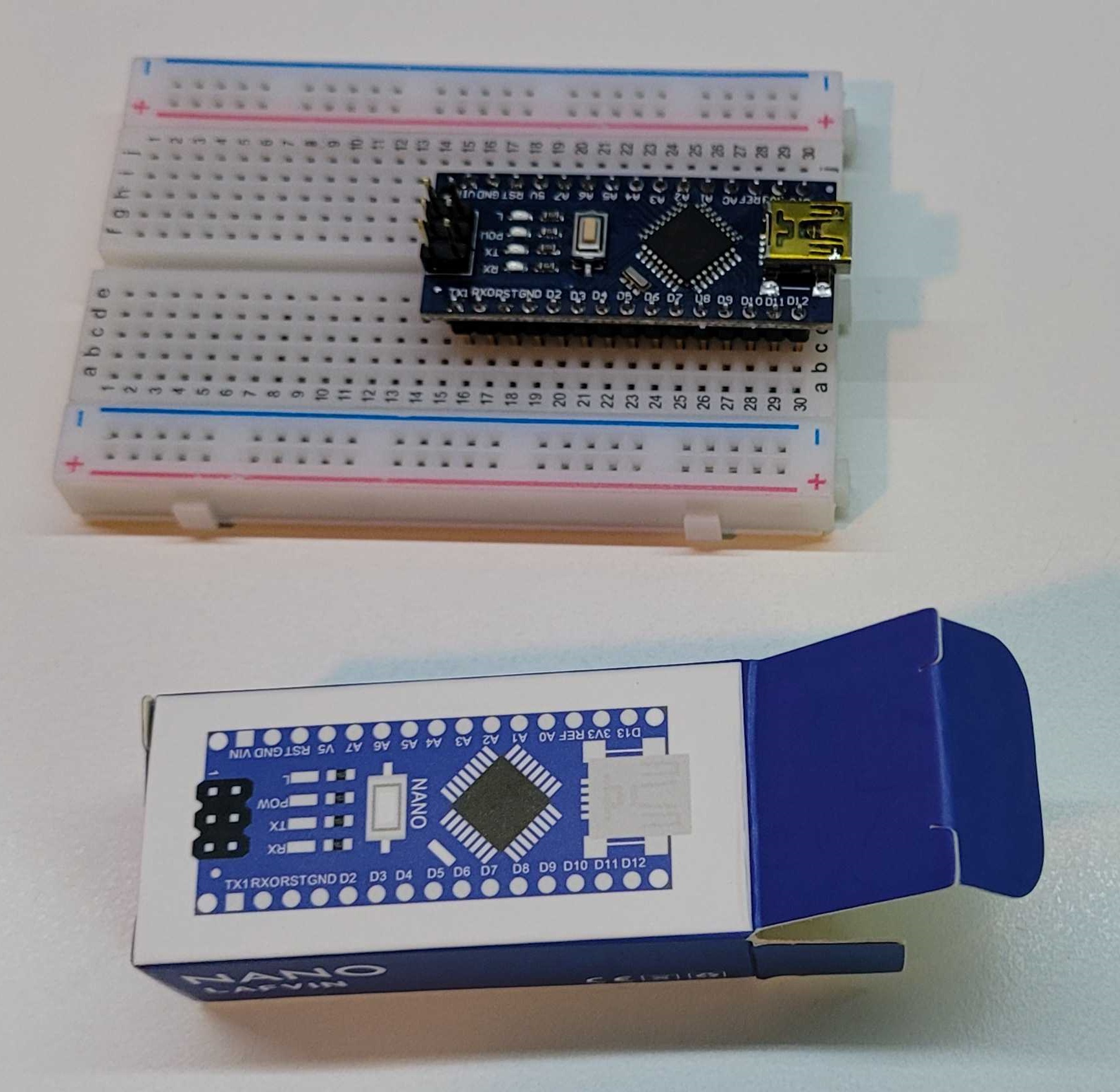
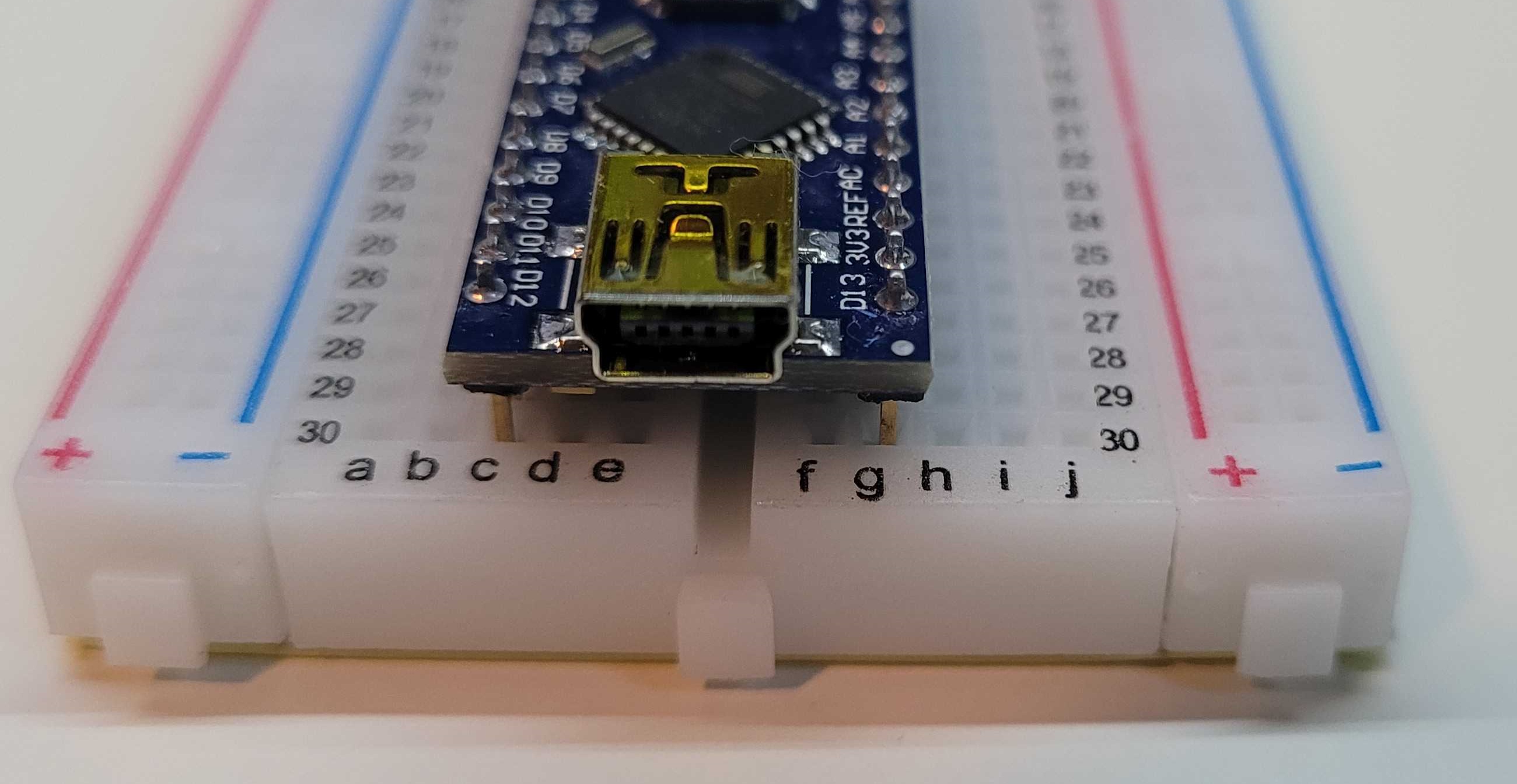
Align the Arduino Nano so that each row of pins straddles the breadboard’s center channel and press down until the pins are fully seated.
4. Connect the MCU USB Cable
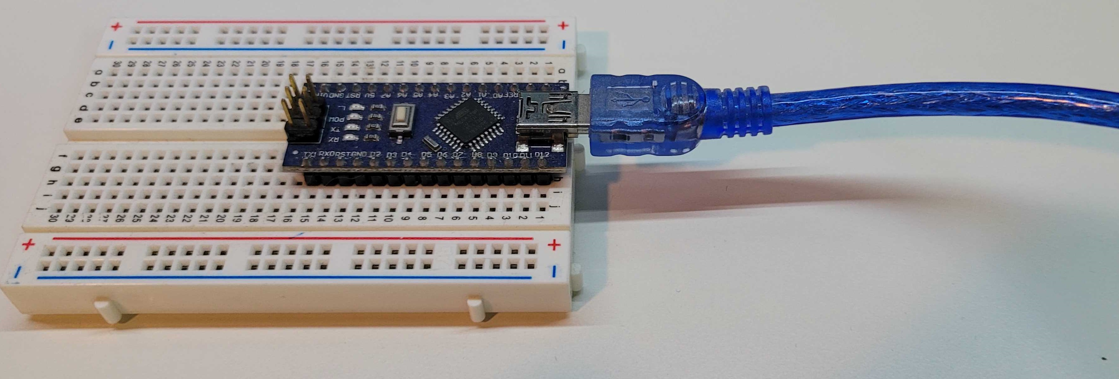
Attach the mini-USB cable to the Arduino Nano. The connector only fits one way—avoid forcing it.
5. Plug the MCU into Your Computer or USB Hub
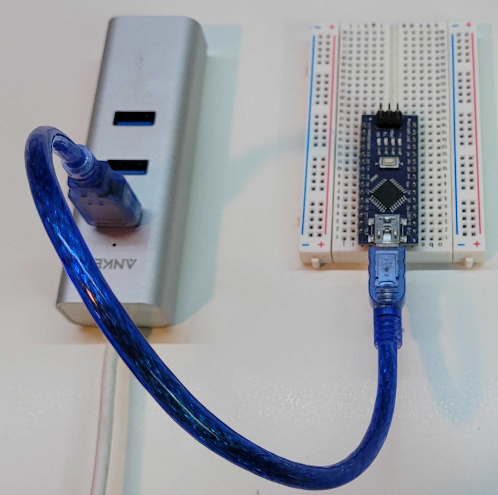
Either connect through a powered USB hub (recommended when sharing ports with the FPGA) or plug the cable directly into your workstation.
6. Connect the FPGA via USB
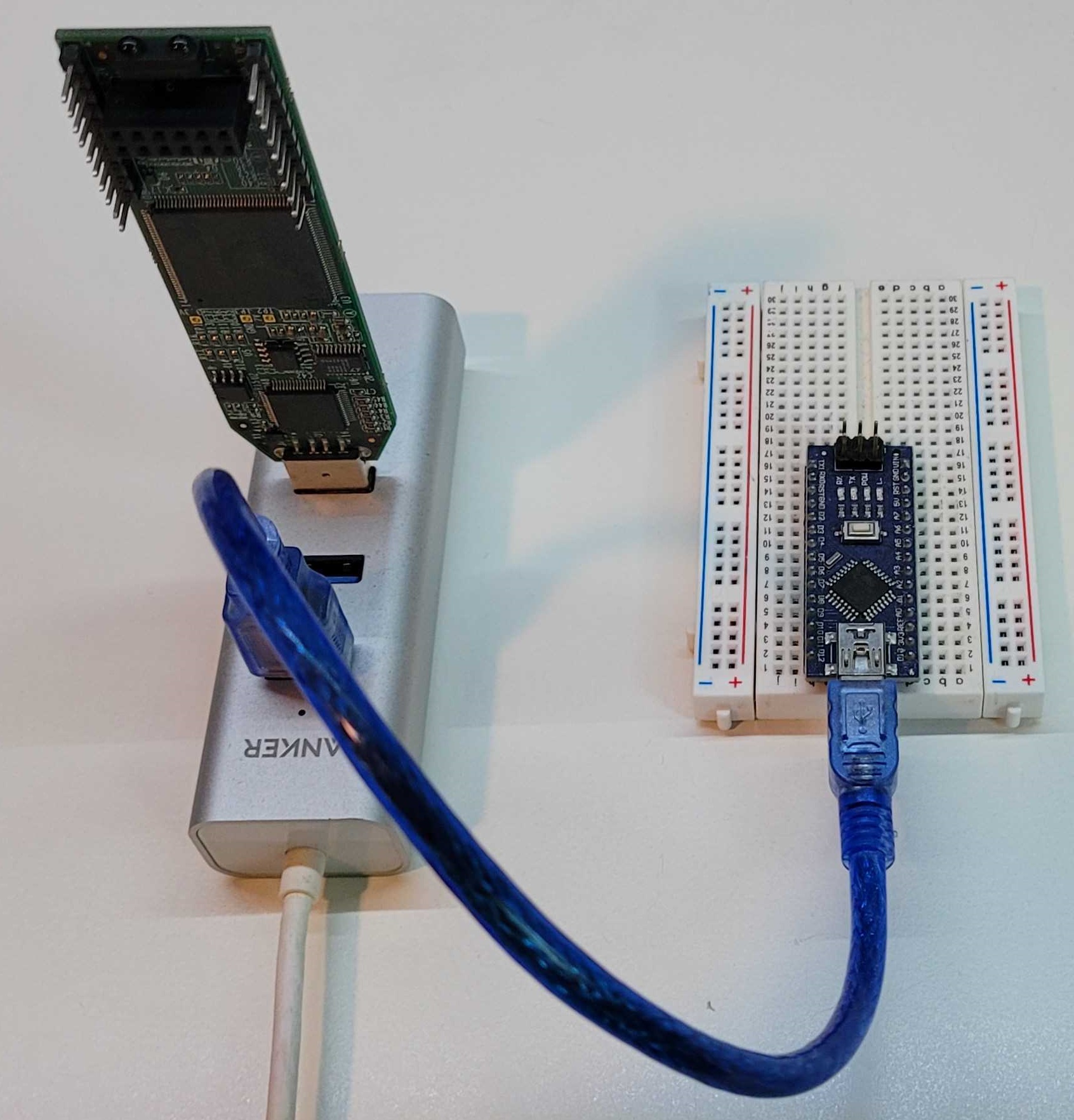
Use the supplied micro-USB cable to power and program the iCEstick. Again, a powered hub is helpful but optional.
7. Bridge Arduino Pins A0 and D2
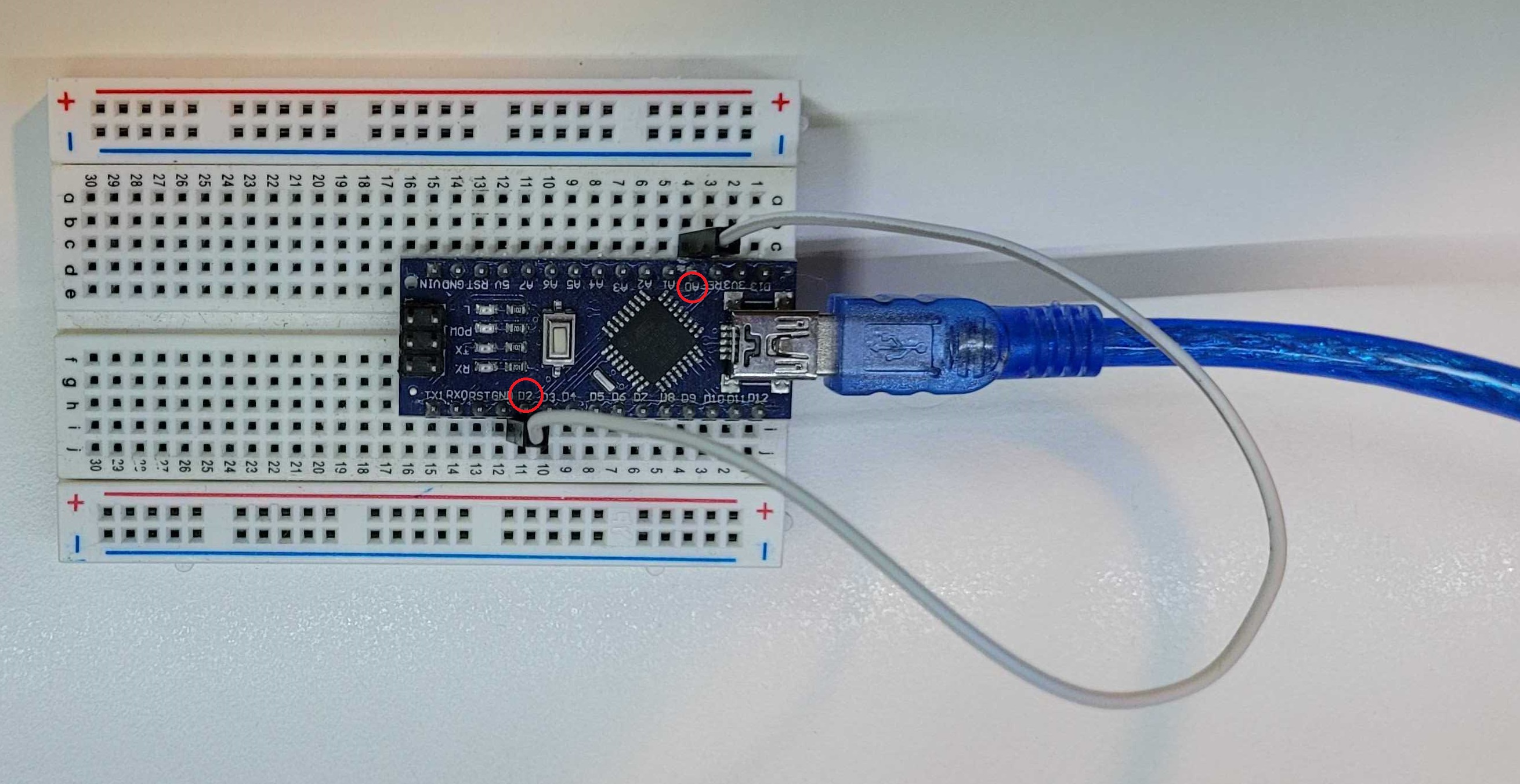
Place a male-to-male jumper between analog pin A0 and digital pin D2. This loopback lets the MCU monitor its own DAC/ADC signal path during experiments.
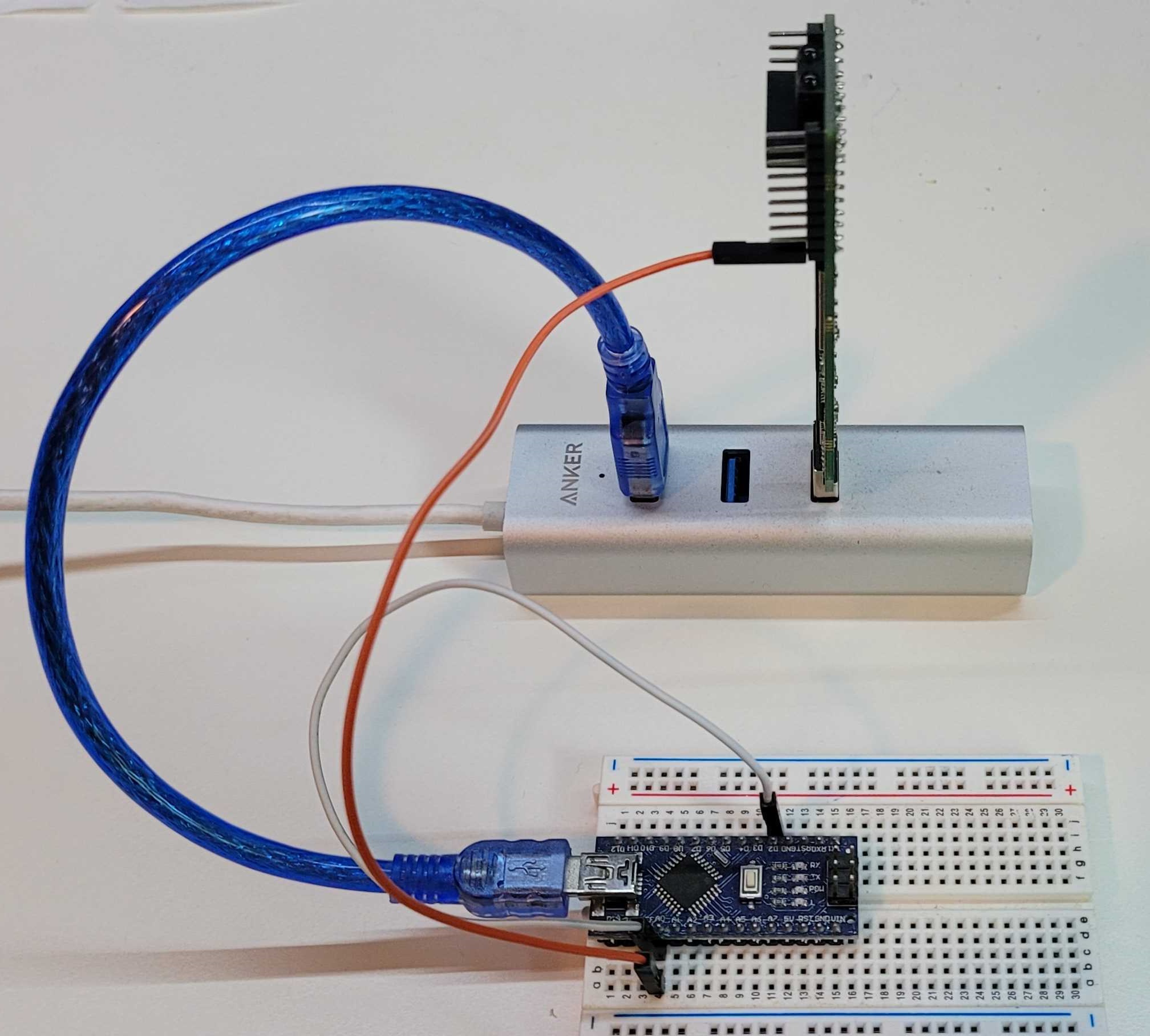
8. Wire the MCU to the FPGA
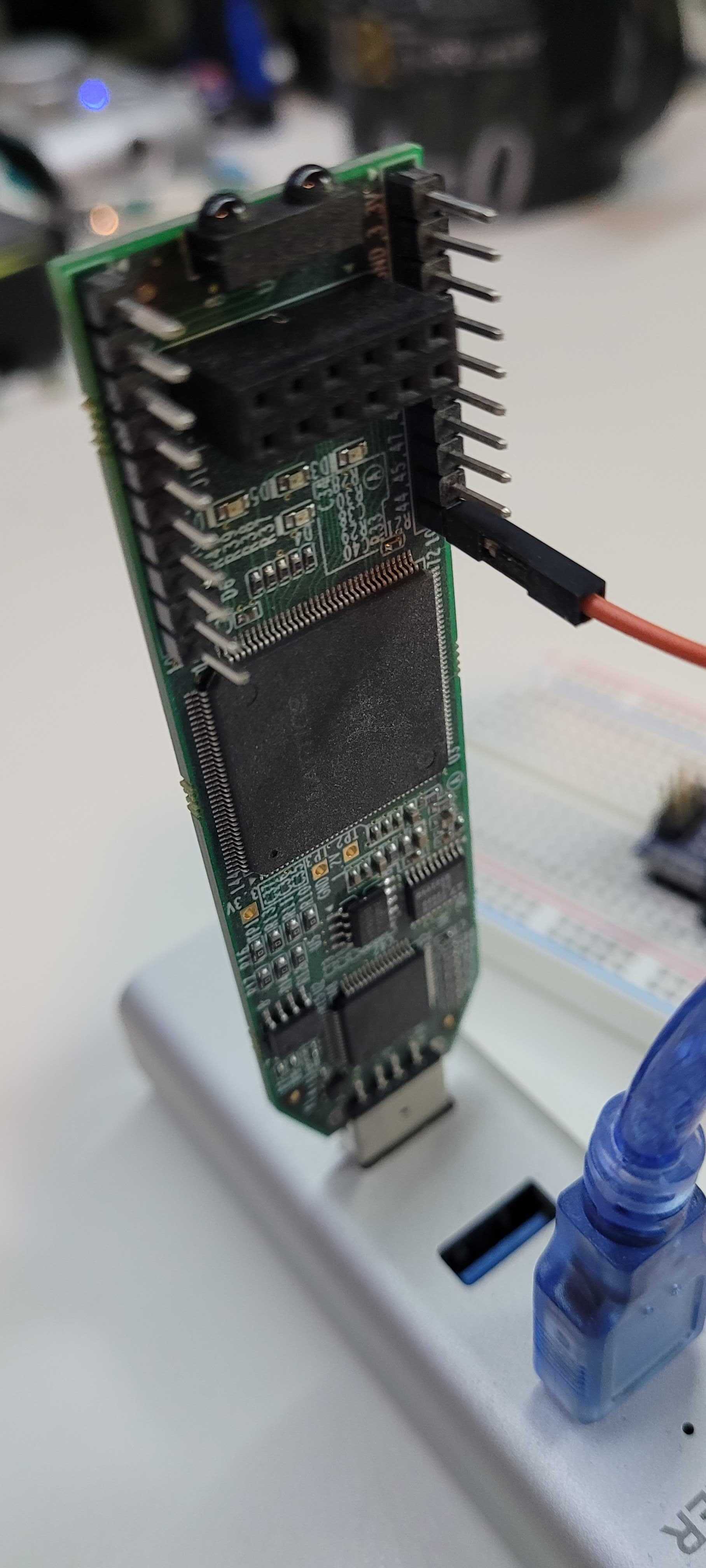 | 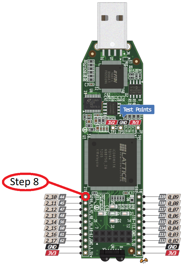 |
Use a male-to-female jumper to connect Arduino pin A0 to FPGA pin 10 (labeled on the iCEstick silkscreen and in the pinout above). Double-check continuity before powering the boards.